Search This Blog

Showing posts with label Mobile Computing. Show all posts
Friday, 3 January 2014

Bluetooth Profiles defined in Bluetooth Specification

0 comments

The Bluetooth Profiles—A Hierarchy of Groups
The Bluetooth specification defines a wide range of profiles, describing many different types of tasks, some of which have not yet been implemented by any device or system. By following the profiles’s procedures, developers can be sure that the applications they create will work with any device that conforms to the Bluetooth specification.This section focuses on those profiles that OS X supports. For information on other profiles, including those still in development, see the Bluetooth specification.
At a minimum, each profile specification contains information on the following topics:
·         Dependencies on other profiles. Every profile depends on the base profile, called the generic access profile, and some also depend on intermediate profiles.
·         Suggested user interface formats. Each profile describes how a user should view the profile so that a consistent user experience is maintained.
·         Specific parts of the Bluetooth protocol stack used by the profile. To perform its task, each profile uses particular options and parameters at each layer of the stack. This may include an outline of the required service record, if appropriate.
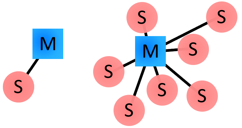
The Bluetooth profiles are organized into a hierarchy of groups, with each group depending upon the features provided by its predecessor. Figure 1-2 illustrates the dependencies of the Bluetooth profiles.


Figure 1-2  The Bluetooth profiles
The Base Profile:
At the base of the profile hierarchy is the generic access profile (GAP), which defines a consistent means to establish a baseband link between Bluetooth devices. In addition to this, the GAP defines:
·         Which features must be implemented in all Bluetooth devices
·         Generic procedures for discovering and linking to devices
·         Basic user-interface terminology
All other profiles are based on the GAP. This allows each profile to take advantage of the features the GAP provides and ensures a high degree of interoperability between applications and devices. It also makes it easier for developers to define new profiles by leveraging existing definitions.
Remaining Profiles:
The service discovery application profile describes how an application should use the SDP (described in “The Bluetooth Protocol Stack”) to discover services on a remote device. As required by the GAP, any Bluetooth device should be able to connect to any other Bluetooth device. Based on this, the service discovery application profile requires that any application be able to find out what services are available on any Bluetooth device it connects to.

The human interface device (HID) profile describes how to communicate with a HID class device using a Bluetooth link. It describes how to use the USB HID protocol to discover a HID class device’s feature set and how a Bluetooth device can support HID services using the L2CAP layer. For more information about the USB HID protocol, see http://www.usb.org.
As its name suggests, the serial port profile defines RS-232 serial-cable emulation for Bluetooth devices. As such, the profile allows legacy applications to use Bluetooth as if it were a serial-port link, without requiring any modification. The serial port profile uses the RFCOMM protocol to provide the serial-port emulation.

The dial-up networking (DUN) profile is built on the serial port profile and describes how a data-terminal device, such as a laptop computer, can use a gateway device, such as a mobile phone or a modem, to access a telephone-based network. Like other profiles built on top of the serial port profile, the virtual serial link created by the lower layers of the Bluetooth protocol stack is transparent to applications using the DUN profile. Thus, the modem driver on the data-terminal device is unaware that it is communicating over Bluetooth. The application on the data-terminal device is similarly unaware that it is not connected to the gateway device by a cable.

The headset profile describes how a Bluetooth enabled headset should communicate with a computer or other Bluetooth device (such as a mobile phone). When connected and configured, the headset can act as the remote device’s audio input and output interface.

The hardcopy cable replacement profile describes how to send rendered data over a Bluetooth link to a device, such as a printer. Although other profiles can be used for printing, the HCRP is specially designed to support hardcopy applications.

The generic object exchange profile provides a generic blueprint for other profiles using the OBEX protocol and defines the client and server roles for devices. As with all OBEX transactions, the generic object exchange profile stipulates that the client initiate all transactions. The profile does not, however, describe how applications should define the objects to exchange or exactly how the applications should implement the exchange. These details are left to the profiles that depend on the generic object exchange profile, namely the object push, file transfer, and synchronization profiles.

The object push profile defines the roles of push server and push client. These roles are analogous to and must interoperate with the server and client device roles the generic object exchange profile defines. The object push profile focuses on a narrow range of object formats for maximum interoperability. The most common of the acceptable formats is the vCard format. If an application needs to exchange data in other formats, it should use another profile, such as the file transfer profile.

The file transfer profile is also dependent on the generic object exchange profile. It provides guidelines for applications that need to exchange objects such as files and folders, instead of the more limited objects supported by the object push profile. The file transfer profile also defines client and server device roles and describes the range of their responsibilities in various scenarios. For example, if a client wishes to browse the available objects on the server, it is required to support the ability to pull from the server a folder-listing object. Likewise, the server is required to respond to this request by providing the folder-listing object.

The synchronization profile is another dependent of the generic object exchange profile. It describes how applications can perform data synchronization, such as between a personal data assistant (PDA) and a computer. Not surprisingly, the synchronization profile, too, defines client and server device roles. The synchronization profile focuses on the exchange of personal information management (PIM) data, such as a to-do list, between Bluetooth enabled devices. A typical usage of this profile would be an application that synchronizes your computer’s and your PDA’s versions of your PIM data. The profile also describes how an application can support the automatic synchronization of data—in other words, synchronization that occurs when devices discover each other, rather than at a user’s command.
Continue reading →

Internal Architecture of Bluetooth Technology

0 comments

Bluetooth Architecture

Bluetooth is both a hardware-based radio system and a software stack that specifies the linkages between layers. This supports flexibility in implementation across different devices and platforms. It also provides robust guidelines for maximum interoperability and compatibility.
In this section, you’ll learn about:
·         The Bluetooth protocol stack. The protocol stack is the core of the Bluetooth specification that defines how the technology works.
·         The Bluetooth profiles. The profiles define how to use Bluetooth technology to accomplish specific tasks.
The Bluetooth Protocol Stack:
The heart of the Bluetooth specification is the Bluetooth protocol stack. By providing well-defined layers of functionality, the Bluetooth specification ensures interoperability of Bluetooth devices and encourages adoption of Bluetooth technology. As you can see in Figure 1-1, these layers range from the low-level radio link to the profiles.


Figure 1-1  The Bluetooth protocol stack
Lower Layers:
At the base of the Bluetooth protocol stack is the radio layer. The radio module in a Bluetooth device is responsible for the modulation and demodulation of data into RF signals for transmission in the air. The radio layer describes the physical characteristics a Bluetooth device’s receiver-transmitter component must have. These include modulation characteristics, radio frequency tolerance, and sensitivity level.

Above the radio layer is the baseband and link controller layer. The Bluetooth specification doesn’t establish a clear distinction between the responsibilities of the baseband and those of the link controller. The best way to think about it is that the baseband portion of the layer is responsible for properly formatting data for transmission to and from the radio layer. In addition, it handles the synchronization of links. The link controller portion of this layer is responsible for carrying out the link manager’s commands and establishing and maintaining the link stipulated by the link manager.

The link manager itself translates the host controller interface (HCI) commands it receives into baseband-level operations. It is responsible for establishing and configuring links and managing power-change requests, among other tasks.  You’ve noticed links mentioned numerous times in the preceding paragraphs. The Bluetooth specification defines two types of links between Bluetooth devices:
·         Synchronous, Connection-Oriented (SCO), for isochronous and voice communication using, for example, headsets
·         Asynchronous, Connectionless (ACL), for data communication, such as the exchange of vCards
Each link type is associated with a specific packet type. A SCO link provides reserved channel bandwidth for communication between a master and a slave, and supports regular, periodic exchange of data with no retransmission of SCO packets.
An ACL link exists between a master and a slave the moment a connection is established. The data packets Bluetooth uses for ACL links all have 142 bits of encoding information in addition to a payload that can be as large as 2712 bits. The extra amount of data encoding heightens transmission security. It also helps to maintain a robust communication link in an environment filled with other devices and common noise.

The HCI (host controller interface) layer acts as a boundary between the lower layers of the Bluetooth protocol stack and the upper layers. The Bluetooth specification defines a standard HCI to support Bluetooth systems that are implemented across two separate processors. For example, a Bluetooth system on a computer might use a Bluetooth module‘s processor to implement the lower layers of the stack (radio, baseband, link controller, and link manager). It might then use its own processor to implement the upper layers (L2CAP, RFCOMM, OBEX, and selected profiles). In this scheme, the lower portion is known as the Bluetooth module and the upper portion as the Bluetooth host.

Of course, it’s not required to partition the Bluetooth stack in this way. Bluetooth headsets, for example, combine the module and host portions of the stack on one processor because they need to be small and self-contained. In such devices, the HCI may not be implemented at all unless device testing is required.
Because the Bluetooth HCI is well defined, you can write drivers that handle different Bluetooth modules from different manufacturers. Apple provides an HCI controller object that supports a USB implementation of the HCI layer.
Upper Layers:
Above the HCI layer are the upper layers of the protocol stack. The first of these is the L2CAP (logical link control and adaptation protocol) layer. The L2CAP is primarily responsible for:
·         Establishing connections across existing ACL links or requesting an ACL link if one does not already exist
·         Multiplexing between different higher layer protocols, such as RFCOMM and SDP, to allow many different applications to use a single ACL link
·         Repackaging the data packets it receives from the higher layers into the form expected by the lower layers
The L2CAP employs the concept of channels to keep track of where data packets come from and where they should go. You can think of a channel as a logical representation of the data flow between the L2CAP layers in remote devices. Because it plays such a central role in the communication between the upper and lower layers of the Bluetooth protocol stack, the L2CAP layer is a required part of every Bluetooth system.
Above the L2CAP layer, the remaining layers of the Bluetooth protocol stack aren’t quite so linearly ordered. However, it makes sense to discuss the service discovery protocol next, because it exists independently of other higher-level protocol layers. In addition, it is common to every Bluetooth device.

The SDP (service discovery protocol) defines actions for both servers and clients of Bluetooth services. The specification defines a service as any feature that is usable by another (remote) Bluetooth device. A single Bluetooth device can be both a server and a client of services. An example of this is the Macintosh computer itself. Using the file transfer profile (described in “The Bluetooth Profiles—A Hierarchy of Groups”) a Macintosh computer can browse the files on another device and allow other devices to browse its files.

An SDP client communicates with an SDP server using a reserved channel on an L2CAP link to find out what services are available. When the client finds the desired service, it requests a separate connection to use the service. The reserved channel is dedicated to SDP communication so that a device always knows how to connect to the SDP service on any other device. An SDP server maintains its own SDP database, which is a set of service records that describe the services the server offers. Along with information describing how a client can connect to the service, the service record contains the service’s UUID, or universally unique identifier.

Also above the L2CAP layer in Figure 1-1 is the RFCOMM layer. The RFCOMM protocol emulates the serial cable line settings and status of an RS-232 serial port. RFCOMM connects to the lower layers of the Bluetooth protocol stack through the L2CAP layer.

By providing serial-port emulation, RFCOMM supports legacy serial-port applications. It also supports the OBEX protocol (discussed next) and several of the Bluetooth profiles (discussed in “The Bluetooth Profiles—A Hierarchy of Groups”).

OBEX (object exchange) is a transfer protocol that defines data objects and a communication protocol two devices can use to easily exchange those objects. Bluetooth adopted OBEX from the IrDA IrOBEX specification because the lower layers of the IrOBEX protocol are very similar to the lower layers of the Bluetooth protocol stack. In addition, the IrOBEX protocol is already widely accepted and therefore a good choice for the Bluetooth SIG, which strives to promote adoption by using existing technologies.
A Bluetooth device wanting to set up an OBEX communication session with another device is considered to be the client device.
1.      The client first sends SDP requests to make sure the other device can act as a server of OBEX services.
2.      If the server device can provide OBEX services, it responds with its OBEX service record. This record contains the RFCOMM channel number the client should use to establish an RFCOMM channel.
3.      Further communication between the two devices is conveyed in packets, which contain requests and responses, and data. The format of the packet is defined by the OBEX session protocol.
Although OBEX can be supported over TCP/IP, this document does not discuss this option (nor is it described in the Bluetooth specification).
Continue reading →

Establishing a Personal Area Network through Bluetooth!

0 comments

Working Principle of Bluetooth Devices

The Bluetooth protocol operates at 2.4GHz in the same unlicensed ISM frequency band where RF protocols like ZigBee and WiFi also exist. There is a standardized set of rules and specifications that differentiates it from other protocols.
Masters, Slaves, and Piconets:
Bluetooth networks (commonly referred to as piconets) use a master/slave model to control when and where devices can send data. In this model, a single master device can be connected to up to seven different slave devices. Any slave device in the piconet can only be connected to a single master.

Examples of Bluetooth master/slave piconet topologies.
The master coordinates communication throughout the piconet. It can send data to any of its slaves and request data from them as well. Slaves are only allowed to transmit to and receive from their master. They can’t talk to other slaves in the piconet.
Bluetooth Addresses and Names:
Every single Bluetooth device has a unique 48-bit address, commonly abbreviated BD_ADDR. This will usually be presented in the form of a 12-digit hexadecimal value. The most-significant half (24 bits) of the address is an organization unique identifier (OUI), which identifies the manufacturer. The lower 24-bits are the more unique part of the address.
This address should be visible on most Bluetooth devices. For example, on this RN-42 Bluetooth Module, the address printed next to “MAC NO.” is 000666422152:

The “000666” portion of that address is the OUI of Roving Networks, the manufacturer of the module. Every RN module will share those upper 24-bits. The “422152” portion of the module is the more unique ID of the device.
Bluetooth devices can also have user-friendly names given to them. These are usually presented to the user, in place of the address, to help identify which device it is.

The rules for device names are less stringent. They can be up to 248 bytes long, and two devices can share the same name. Sometimes the unique digits of the address might be included in the name to help differentiate devices.
Connection Process:
Creating a Bluetooth connection between two devices is a multi-step process involving three progressive states:
1.      Inquiry – If two Bluetooth devices know absolutely nothing about each other, one must run an inquiry to try to discoverthe other. One device sends out the inquiry request, and any device listening for such a request will respond with its address, and possibly its name and other information.
2.      Paging (Connecting) – Paging is the process of forming a connection between two Bluetooth devices. Before this connection can be initiated, each device needs to know the address of the other (found in the inquiry process).
3.      Connection – After a device has completed the paging process, it enters the connection state. While connected, a device can either be actively participating or it can be put into a low power sleep mode.
o    Active Mode – This is the regular connected mode, where the device is actively transmitting or receiving data.
o    Sniff Mode – This is a power-saving mode, where the device is less active. It’ll sleep and only listen for transmissions at a set interval (e.g. every 100ms).
o    Hold Mode – Hold mode is a temporary, power-saving mode where a device sleeps for a defined period and then returns back to active mode when that interval has passed. The master can command a slave device to hold.
o    Park Mode – Park is the deepest of sleep modes. A master can command a slave to “park”, and that slave will become inactive until the master tells it to wake back up.
Bonding and Pairing:
When two Bluetooth devices share a special affinity for each other, they can be bonded together. Bonded devicesautomatically establish a connection whenever they’re close enough. When I start up my car, for example, the phone in my pocket immediately connects to the car’s Bluetooth system because they share a bond. No UI interactions are required!
Bonds are created through one-time a process called pairing. When devices pair up, they share their addresses, names, and profiles, and usually store them in memory. The also share a common secret key, which allows them to bond whenever they’re together in the future.
Pairing usually requires an authentication process where a user must validate the connection between devices. The flow of the authentication process varies and usually depends on the interface capabilities of one device or the other. Sometimes pairing is a simple “Just Works” operation, where the click of a button is all it takes to pair (this is common for devices with no UI, like headsets). Other times pairing involves matching 6-digit numeric codes. Older, legacy (v2.0 and earlier), pairing processes involve the entering of a common PIN code on each device. The PIN code can range in length and complexity from four numbers (e.g. “0000” or “1234”) to a 16-character alphanumeric string.
Continue reading →
Monday, 30 December 2013

Use of Wireless Communication in Mobile Computing

0 comments
Wireless Communication
            A wired medium provides a reliable, guided link that conducts an electric signal associated with the transmission of information from one fixed terminal to another.  There are a number of alternatives for wired connection that include twisted pair (TP) telephone wiring for high-speed LANs, coaxial cables used for television distribution, and optical fiber used in the backbone of long-haul connections.
            Wires act as filters that limit the maximum transmitted data rate of the channel because of band limiting frequency response characteristics.  The signal passing through a wire also radiates outside of the wire to some extent which can cause interference to close-by radios or other wired transmissions.  These characteristics differ from one wired medium to another.  Laying additional cables in general can duplicate the wired medium, and thereby increase the bandwidth.
Wireless Transmission:
Compared with wired media, the wireless medium is unreliable, has a low bandwidth, and is of broadcast nature; however, it supports mobility due to its tetherless nature.  Different signals through wired media are physically conducted through different wires, but all wireless transmissions share the same medium – air.  Thus it is the frequency of operation and the legality of access to the band that differentiates a variety of alternative for wireless networking.
Wireless networks operate around 1 GHz (cellular), 2 GHz (PCS and WLANs), 5 GHz (WLANs), 28-60 GHz (Local Multipoint Distribution Service [LMDS] and point-to-point base station connections), and IR frequencies for optical communications.  These bands are either licensed, like cellular and PCS bands, or unlicensed, like the ISM bands or U-NII bands.  As the frequency of operation and data rates increase, the hardware implementation cost increases, and the ability of a radio signal to penetrate walls decreases.
The electronic cost has become less significant with time, but in-building penetration and licensed versus unlicensed frequency bands have become an important differentiation.  For frequencies of up to a few GHz, the signal penetrates through the walls, allowing indoor applications with minimal wireless infrastructure inside a building.  At higher frequencies a signal that is generated outdoors does not penetrate into buildings, and the signal generated indoors stays confined to a room.  This phenomenon imposes restrictions on the selection of a suitable band for a wireless application.
Difference between Wired and Wireless Medium:
Wired media provide us an easy means to increase capacity – we can lay more wires where required if it affordable.  With the wireless medium, we are restricted to a limited available band for operation, and we cannot obtain new bands or easily duplicate the medium to accommodate more users.  As a result, researchers have developed a number of techniques to increase the capacity of wireless networks to support more users with a fixed bandwidth. 
The simplest method, comparable to laying new wires in wired networks, is to use a cellular architecture that reuses the frequency of operation when two cells are at an adequate distance from one another.  Then, to further increase the capacity of the cellular network, one may reduce the size of the cells.
In a wired network, doubling the number of wired connections allows twice the number of users at the expense of twice the wired connections to the terminals.  In a wireless network, reducing the size of the cells by half allows twice as many users as in one cell.  Reduction of the size of the cell increases the cost and complexity of the infrastructure that interconnects the cells.
Wireless Networks:
            A wireless network, which uses high-frequency radio waves rather than wires to communicate between nodes, is another option for home or business networking.  Individuals and organizations can use this option to expand their existing wired network or to go completely wireless.  Wireless allows for devices to be shared without networking cable which increases mobility but decreases range.  There are two main types of wireless networking; peer to peer or ad-hoc and infrastructure. (Wi-fi.com)
            An ad-hoc or peer-to-peer wireless network consists of a number of computers each equipped with a wireless networking interface card. Each computer can communicate directly with all of the other wireless enabled computers. They can share files and printers this way, but may not be able to access wired LAN resources, unless one of the computers acts as a bridge to the wired LAN using special software.
            An infrastructure wireless network consists of an access point or a base station.  In this type of network the access point acts like a hub, providing connectivity for the wireless computers. It can connect or bridge the wireless LAN to a wired LAN, allowing wireless computer access to LAN resources, such as file servers or existing Internet Connectivity. (compnetworking.about.com)
            There are four basic types of transmissions standards for wireless networking.  These types are produced by the Institute of Electrical and Electronic Engineers (IEEE).  These standards define all aspects of radio frequency wireless networking.  They have established four transmission standards; 802.11, 802.11a, 802.11b, 802.11g.
            The basic differences between these four types are connection speed and radio frequency.  802.11 and 802.11b are the slowest at 1 or 2 Mbps and 5.5 and 11Mbps respectively.  They both operate off of the 2.4 GHz radio frequency.  802.11a operates off of a 5 GHz frequency and can transmit up to 54 Mbps and the 802.11g operates off of the 2.4 GHz frequency and can transmit up to 54 Mbps.  Actual transmission speeds vary depending on such factors as the number and size of the physical barriers within the network and any interference in the radio transmissions. (Wi-fi.com)
            Wireless networks are reliable, but when interfered with it can reduce the range and the quality of the signal.  Interference can be caused by other devices operating on the same radio frequency and it is very hard to control the addition of new devices on the same frequency.   Usually if your wireless range is compromised considerably, more than likely, interference is to blame. (Laudon)
A major cause of interference with any radio signals are the materials in your surroundings, especially metallic substances, which have a tendency to reflect radio signals.  Needless to say, the potential sources of metal around a home are numerous--things like metal studs, nails, building insulation with a foil backing and even lead paint can all possibly reduce the quality of the wireless radio signal. Materials with a high density, like concrete, tend to be harder for radio signals to penetrate, absorbing more of the energy. Other devices utilizing the same frequency can also result in interference with your wireless. For example, the 2.4GHz frequency used by 802.11b-based wireless products to communicate with each other.  Wireless devices don't have this frequency all to themselves. In a business environment, other devices that use the 2.4GHz band include microwave ovens and certain cordless phones. (Laundon)
            On the other hand, many wireless networks can increase the range of the signal by using many different types of hardware devices. A wireless extender can be used to relay the radio frequency from one point to another without losing signal strength. Even though this device extends the range of a wireless signal it has some drawbacks.  One drawback is that it extends the signal, but the transmission speed will be slowed.
            There are many benefits to a wireless network.  The most important one is the option to expand your current wired network to other areas of your organization where it would otherwise not be cost effective or practical to do so.  An organization can also install a wireless network without physically disrupting the current workplace or wired network. (Wi-Fi.org) Wireless networks are far easier to move than a wired network and adding users to an existing wireless network is easy.  Organizations opt for a wireless network in conference rooms, lobbies and offices where adding to the existing wired network may be too expensive to do so.
Continue reading →

Mobile Computing and Use of Networks in it!

0 comments

Mobile Computing and Networks

Mobile computing can be defined as a computing environment over physical mobility.  The user of a mobile computing environment will be able to access data, information or other logical objects from any device in any network while on the move.  Mobile computing system allows a user to perform a task from anywhere using a computing device in the public (the Web), corporate (business information) and personal information spaces (medical record, address book).

            While on the move, the preferred device will be a mobile device, while back at home or in the office the device could be a desktop computer.  To make the mobile computing environment ubiquitous, it is necessary that the communication bearer is spread over both wired and wireless media.

            In mobile computing, computing environment is mobile and it moves along with the user.  We can define a computing environment as mobile if it supports one or more of the following characteristics:

User Mobility:  User should be able to move from one physical location to another location and use the same service.  Example could be a user moves from London to New York and uses Internet to access the corporate application the same way the user uses in the home office.

Network Mobility:  User should be able to move from one network to another network and use the same service.  Example could be a user moves from Hong Kong to New Delhi and uses the same GSM phone to access the corporate application through WAP (Wireless Application Protocol).  In home network he uses this service over GPRS (General Packet Radio Service) whereas in Delhi he accesses it over the GSM network.

Bearer Mobility:  User should be able to move from one bearer to another and use the same service.  Example could be a user using a service through WAP bearer in his home network in Bangalore, moves to Coimbatore, where WAP is not supported.  He can switch over to voice or SMS (Short Message Service) bearer to access the same application.

Device Mobility:  User should be able to move from one device to another and use the same service.  Example could be sales representatives using their desktop computer in home office.  During the day while they are on the street they would like to use their Palmtop to access the same application.

The device for mobile computing can be either a computing device or a communication device.  In computing device category it can be a desktop computer, laptop computer, or a palmtop computer.  On the communication device side, it can be fixed line telephone, a mobile telephone or a digital T.V.  Usage of these devices are becoming more and more integrated to task flow where fixed and mobile, computing and communication devices are used together.

Use of Networks in Mobile Computing:
            Mobile computing uses different types of networks.  They are listed below:
  1. Fixed telephone network
  2. GSM
  3. GPRS
  4. ATM (Asynchronous Transfer Mode) Network
  5. Frame Relay Network
  6. ISDN (Integrated Service Digital Network)
  7. CDMA
  8. CDPD (Cellular Digital Packet Data) Network
  9. DSL (Digital Subscriber Loop) Network
  10. Dial-up Network
  11. WiFi (Wireless Fidelity) Network
  12. 802.11 (Wireless LAN)
  13. Bluetooth Network
  14. Ethernet (Wired network)
  15. Broadband Network etc.
Wireline Network:
            This is a network, which is designed over wire or tangible conductors.  This network is called fixed or wireline network.  Fixed telephone networks over copper and fiber-optic will be part of this network family.  Broadband networks over DSL or cable will also be part of wireline networks.
            Wireline networks are generally public networks and cover wide areas.  Though microwave or satellite networks do not use wire, when a telephone network uses microwave or satellite as a part of infrastructure, it is considered part of wireline networks.  When we connect to ISPs it is generally a wireline network.  The Internet backbone is a wireline network as well.
Wireless Network:
            Mobile networks are generally termed as wireless network.  This includes wireless networks used by radio taxis, one way and two way pager, cellular phones.  Example will be PCS (Personal Cellular System), AMPS (Advanced Mobile Phone System), GSM, CDMA, DoCoMo, GPRS etc.
            WiLL (Wireless in Local Loop) networks using different types of technologies are part of wireless networks as well.  In a wireless network the last mile is wireless and works over radio interface.  In a wireless network other than the radio interface rest of the network is wireline, this is generally called the PLMN (Public Land Mobile Network).
Ad-hoc Network:
            In Latin, ad hoc literally means ‘for this purpose only’.  An ad-hoc (or spontaneous) network is a small area network, especially one with wireless or temporary plug-in connections.  In these networks, some of the devices are part of the network only for the duration of a communication session.  An ad-hoc network is also formed when mobile, or portable devices, operate in close proximity of each other or with the rest of the network. 
The term ‘ad hoc’ has been applied to networks in which new devices can be quickly added using, for example, Bluetooth or Wireless LAN (802.11x).  In these networks, devices communicate with the computer and other devices using wireless transmission.  Typically based on short-range wireless technology, these networks don’t require subscription services or carrier networks.
Bearers:
For different type of networks, there are different types of transport bearers.  These can be TCP/IP, http, protocols for dialup connection.  For GSM, it could be SMS, USSD (Unstructured Supplementary Service Data) or WAP.  For mobile or fixed phone, it will be voice.


Continue reading →