Search This Blog

Showing posts with label Computer Networks. Show all posts
Tuesday, 22 November 2011

Physical Layer and Media used in Networks

0 comments

-->
THE PHYSICAL LAYER! 
The physical layer coordinates the functions required to carry a bit stream over a medium. It deals with the mechanical and electrical specifications of the interface and transmission media. It also defines the procedures and functions that physical devices and interfaces have to perform for transmission to occur.
The following are the issues that are to be dealt with the physical layer for the movement of individual bits from one hop (node) to the next:
  1. Physical characteristics of interfaces and medium
  2. Representation of bits
  3. Data rate
  4. Synchronization of bits
  5. Line configuration
  6. Physical topology
  7. Transmission mode
Physical Characteristics of Interfaces and Medium:
The physical layer defines the characteristics of the interface between the devices and the transmission medium. It also defines the type of transmission medium.
Representation of Bits:
The physical layer receives data from the Data Link layer in the form of bits (0s and 1s) and adds header and footer information to it. Before transmission through the media, the bits must be encoded into signals – electrical or optical. The type of encoding, (i.e., how 0s and 1s are changed to signal) is defined in the protocols of physical layer.
Data Rate:
The number of bits that can be sent each second on the transmission media is also defined by the physical layer.
Synchronization of Bits:
The sender and the receiver not only must use the same bit rate but also must be synchronized at the bit level. In other words, the sender and the receiver clocks must be synchronized.
Line Configuration:
The physical layer defines how a device can be connected to the media. It defines two types of connectivity: Point-to-Point and Multi-point. In point-to-point configuration, two devices are connected through a dedicated line. In a multi-point configuration, the media (link) is shared among several devices.
Physical Topology:
The physical topology refers to the method of arranging and linking all the devices that are part of a network. There are four different topologies introduced namely mesh, ring, bus and star. The devices may be connected in a network using one or more topologies. The combination of two or more topologies is called hybrid topology.
Transmission Mode:
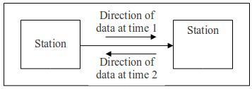
The physical layer defines the direction of transmission between two devices in three ways: simplex, half-duplex or full-duplex. In simplex mode, only one device can send; the other can only receive. But, in duplex mode, both devices involved in transmission can send and receive data simultaneously. Though two way communications is possible, only one can communicate at a time.

Physical Layer and Media
The physical layer is the first layer in the network model that actually interacts with the transmission media, the physical part of the network. This layer is involved in physically carrying of information from one node to another in the network.
The physical layer provides some services to the data link layer. One of the services it provides is the conversion of data (the data which comes from the data link layer in the form of stream of bits) into signals.

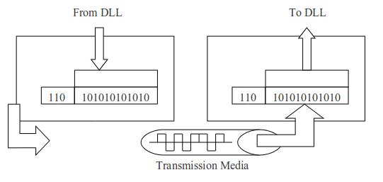
Fig. : Physical Layer
The physical layer must also take care of the physical network, the transmission media. It must decide on the direction of data flow, number of logical channels for transporting data coming from different sources, etc.
Data and Signals:
One of the major functions of the physical layer is to move data in the form of electromagnetic signals across the transmission medium. Generally, the data usable to a person or application are not in a form that can be transmitted over a network.
The transmission media works by conducting energy along the physical path. To send data along the physical path, they must be converted to electromagnetic signals before transmission. Both data and the signals that represent them can be either analog or digital in form.
Analog and Digital Data:
Data can be analog or digital in form. The term analog data refers to the information that is continuous; but digital data refers to the information that has discrete states. For example, an analog clock that has hour, minute and second hand gives information in a continuous form; the movements of the hands are continuous. On the other hand, a digital clock that reports the hours and the minutes will change suddenly from 8:05 to 8:06. Such digital data take on discrete values.
Data are always stored in a computer in the form of digits (0s and 1s). They can be converted to digital signals or modulated into analog signals for transmission across a medium.
Analog and Digital Signals:
Signals can be either analog or digital. An analog signal has infinitely many levels of intensity over a period of time.  As the wave moves from value A to value B, it passes through and includes an infinite number of values along its path.
A digital signal, on the other hand, can have only a limited number of defined values.  Although each value can be any number, it is often as simple as 1 and 0.  Sine wave and Square wave are examples of analog and digital signals respectively.
Digital Transmission:
A computer network is designed to send information from one point to another.  This information needs to be converted to either digital signals or analog signals for transmission.  For instance, when someone speaks, an analog wave is created in the air.  This can be captured by a microphone and converted to an analog signal or sampled and converted to a digital signal.
An analog signal is a continuously varying electromagnetic wave that may be propagated over a variety of media, which includes both guided and unguided media.  A digital signal is a sequence of voltage pulses that may be transmitted over a wired medium; for example, a constant positive voltage level may represent binary 1 and a constant negative voltage level may represent binary 0.
Generally, analog data are a function of time that may be represented well by an electromagnetic signal.  And the digital data are represented by digital signals, with different voltage levels for each of the two binary digits.
Digital data can also be represented by analog signals by use of a modem (Modulator/Demodulator).  The modem converts a series of binary (two-valued) voltage pulses into analog signals by encoding the digital data onto a carrier frequency.  At the other end of the line, another modem demodulates the signal to recover the original data.
Transmission along the Medium:
Both analog and digital signals may be transmitted on any suitable transmission media.  The way these signals are treated is a function of the transmission system.  Analog transmission is a means of transmitting analog signals without regard to their content; the signal may represent analog data or digital data.
In either case (analog or digital transmission), the analog signal will become weaker (attenuate) after a certain distance.  To achieve long distance, the analog transmission system includes amplifiers that boost the energy in the signal.  Unfortunately, the amplifier also boosts the noise components.
Digital transmission, in contrast, is concerned with the content of the signal.  A digital signal can be transmitted only a limited distance before attenuation, noise and other impairments endanger the integrity of the data.  To achieve greater distance, repeaters are used.  A repeater receives the digital signal, recovers the pattern of 1s and 0s, and retransmits a new signal.
Continue reading →

Topologies in Computer Networks

0 comments
NETWORK TOPOLOGIES!  

The term topology refers to the way in which a network is laid out physically. It is a combination of two or more links, each connecting a number of devices to it. It shows the logical representation between the links and the nodes that are connected to them. There are four basic topologies of networks: mesh, star, bus and ring.

Fig. : Topologies used in Computer Networks

Bus TopologyMesh Topology
In mesh topology, every device has a dedicated point-to-point link to every other device. Each such a link carries the traffic only between the two devices it connects. To find the total number of physical links in a fully connected mesh network having n nodes, we use the formula:
n (n – 1)
However, if each physical link allows communication in both directions (i.e., communication in duplex mode), we can calculate the number of links by dividing the total value by 2:
n (n – 1) / 2
To accommodate n devices (workstations) in a mesh topology, every device on the network must have n-1 input/output (I/O) ports to connect to the other n-1 stations. The following figure shows a network using mesh topology with n workstations:

Fig. : A fully connected mesh topology
There are certain advantages and disadvantages of using mesh topology for forming a network. They are as follows:
Advantages:
  1. The user of dedicated links guarantees no traffic problem that can occur when links are shared by multiple devices.
  2. It is robust, i.e., if one link fails, it will not affect the traffic in the entire network.
  3. There is an advantage of privacy or security. As messages travel along a dedicated line, only the intended recipient can obtain it.
  4. It makes fault identification and fault isolation easy.
Disadvantages:
  1. As every device is connected with every other device, installation and reconnection are difficult.
  2. The sheer bulk of the wiring can be greater than the available space (in walls, ceilings or floors) can accommodate.
  3. The hardware required to connect each link (I/O ports and cable) can be prohibitively expensive.
Due to the above said points, a mesh topology is usually implemented in a limited fashion, for e.g., as a backbone connecting the main computers of a hybrid network that can include several other topologies.

Star Topology
In star topology, each device has a dedicated point-to-point link only to a central controller, usually called a hub. The devices are not directly linked to each other, but through the controller, which acts as an exchange. If one device wants to send data to another, it sends the data to the controller, which then relays the data to the other connected device in the network.


Fig. : A Star topology connecting four stations
Some of the advantages and disadvantages of star topology are discussed below:
Advantages:
  1. A star topology is less expensive than a mesh topology, because of less number of links used for connecting the devices. Each device needs only one link and one I/O port to connect it to any other devices.
  2. Easy to install and reconfigure. Adding, moving or removing a device from the network involves only on3 Pageviewse connection: the connection between the device and the hub.
  3. It is robust in managing the failures in links between its devices. If one link fails, only that link is affected. All other links remain active. Moreover, the hub helps the administrator to identify the fault link easily and to rectify it.
Disadvantages:
  1. The major disadvantage of this topology lies in the dependency of the whole network on one single point, the hub. If the hub goes down, the whole system is dead.
  2. It requires more cabling than some other topologies, due to the reason that each device must be connected to the central hub.
Due these advantages and disadvantages, this topology is used mainly in LAN, especially in High-speed LANs.

Bus Topology
Bus topology is a multipoint network, which uses a long cable as a backbone to the network, to which all the devices are connected. All the devices are connected to the bus cable by drop lines and taps.

Fig. : A Network using Bus Topology
A drop line is a connection running between the device and the main cable. A tap is a connector that either splices into the main cable or punctures the sheathing of a cable to create a contact with the metallic core. As a signal travels along the backbone, some of its energy is transformed into heat. Therefore, it becomes weaker and weaker as it travels farther and farther.
There is some reflection of signals at the taps, which causes degradation in quality of signals transmitted. This degradation can be controlled by limiting the number and spacing of devices connected to a given length of cable. Adding new devices may therefore require modification or replacement of the backbone. The advantages and disadvantages of this topology are as follows:
Advantages:
  1. Ease of installation.
  2. Uses less cabling than mesh or star topologies.
  3. Used mainly in the design of early LANs and later in Ethernet LANs.
Disadvantages:
  1. It involves some difficulty in reconnection and fault isolation.
  2. It finds difficulty in adding new devices.
  3. It creates noise in the network, when there is a damage or fault in the cable. Moreover, a fault or a break in the media stops all transmission, even between the devices on the same side of the problem due to noise.
Ring Topology
In ring topology, each device has a dedicated point-to-point connection with only two devices that are located at both sides of it. Each device in the ring acts either as a receiver or repeater. When it receives any data, it checks whether the incoming data belong to it or not. If it belongs to it, it just receives the data. Otherwise, it regenerates the signal and passes it on to the system next to it.
The data flow in a ring network is always unidirectional. Though each device is connected to two other devices in the ring, it always receives data from any one of the two devices. A signal is passed along the ring from device to device, until it reaches its destination. The following figure shows a ring topology connection with six stations:

Fig. : A Ring network connecting 6 workstations
Ring topology also has its merits and demerits. The following list displays it:
Advantages:
  1. Easy to install and reconfigure. This is due to the fact that the addition or removal of a device in the network requires change in only two places.
  2. The fault isolation is simplified. The ring is designed in such a way that it can raise an alarm, when a particular workstation doesn’t receive the signal passed along the ring.
Disadvantages:
  1. Transferring the signal always takes place in one direction, which results in taking a long route to deliver the data even to its neighbor at the sending side.
  2. In a simple ring, a break in the ring can disable the entire network.
Hybrid Topology:
Hybrid topology is a combination of two or more topologies, among which one acts as a backbone.
Continue reading →
Sunday, 20 November 2011

Data Flow in a Network

0 comments
NETWORK DATA FLOW!


Data communication between two systems can take place in three different modes: Simplex, half-duplex and full-duplex. In simplex mode, the communication is unidirectional, i.e., data flow takes place only one direction. In this mode, one of the two communication devices acts as a sender, and the other as a receiver. The data flow always takes place from the sender to the receiver. The communication can’t take place from the other side.
Examples for simplex communication are simple I/O devices like monitor or keyboard. Such devices always work in only one direction. They are used either for input or output purposes. But they can make use of the entire capacity of the channel to send the data in one direction.

Fig. : Simplex mode of communication
Half Duplex:
In this mode, each device can transmit as well as receive, but not at the same time. When one device is sending, the other can only receive, and vice versa. This mode of transmission is like a narrow bridge, which allows only one vehicle to move on it at either direction. When vehicles are moving in one direction, the vehicles from the other side must wait. Walkie Talkie and CB (Citizens Band) radios are both half-duplex systems.
The half-duplex mode is used in cases where there is no need for communication in both directions at the same time; the entire capacity of the channel can be utilized for each direction. The devices involved in half-duplex communication are called workstations. The workstations share the common communication media between them on timely basis but with fullest capacity.

Fig. : Half-duplex mode of communication
Full Duplex:
The full-duplex mode is like a two-way street with traffic flowing in both directions at the same time. This mode allows both the sender and the receiver to transmit and receive simultaneously. This mode of communication is also known as Duplex mode. Duplex mode allows signals moving in one direction share the capacity of the link with the signals moving in the other direction.
One common example of this type of communication is the telephone network. In telephone network, two people can talk to each other at the same time. This mode of data transfer is required when data transmission takes place from both sides of the network simultaneously. The capacity of the channel, however, must be divided between the two parties.

Fig. : Duplex communication
Node:
A node is a device, which is connected to a network via a communication link like cable. It can be a computer, printer or any other device capable of sending and/or receiving data gathered by other nodes on the network.
Distributed Processing:
Distributed processing is a way of performing a task in a network. In distributed processing, multiple computers are used to share the task and each and every computer performs certain aspects of the entire process.
Network Criteria:
Some of the important criteria that must be met by a computer network are: performance, reliability and security. Performance refers to the speed at which the data transmission takes place in a network. The performance of a network depends on a number of factors, which include the number of users, the type of transmission medium used, the capacities of the connected hardware and the efficiency of the software.
The performance of a network is often evaluated by two metrics: Throughput and Delay. Throughput determines the efficiency based on the number of packets transmitted at a specific period of time. It shows the frequency of data transfer in a network.
Delay is a metric, which indicates the time taken for transmitting the data from one place to another. Delay can be measured by calculating the time, such as transit time and response time. Transit time is the amount of time required for a message to travel from one device to another. Response time is the elapsed time between an inquiry and a response.
Reliability is a criterion which determines the frequency of failure in a network. It also involves the time taken for a link to recover from a failure, and the networks robustness in a catastrophe. Security deals with protecting data from unauthorized users, protection from loss or damage, and implementing policies and procedures for recovery from breaches and data loses.
Types of Network Connections:
A network comprises of two or more communication devices and a media for communication called link. A link is a communication pathway that transfers data from one device to another. All the computers in a network are connected to each other in any one of two ways:
  1. Point-to-Point connection and
  2. Multi Point connection
Point-to-Point Connection:
A point-to-point link connects two computers in a network using a dedicated link. The entire capacity of the link is reserved for transmission between those two devices. Most point-to-point connections use an actual length of wire or cable to connect the two ends.

Fig. : Point-to-Point Connection
Multipoint Connection:
A multi point (also called as multi drop) connection is a link which connects two or more devices through a common media. All the devices that are connected to the link share it among themselves.
In this type of connection, the capacity of the channel is shared either spatially or temporarily. If several devices can use the link simultaneously, it is a spatially shared connection. If users must take turns, it is a time shared connection.

Fig. : Multi point Connection
Continue reading →
Saturday, 19 November 2011

ISO/OSI Model of Networking

1 comments

ISO / OSI MODEL! 
The Open Systems Interconnection (OSI) model is a standard set by ISO to cover all aspects of network communications. It was introduced in the late 1970s. An Open System is a set of protocols that allows any two different systems to communicate regardless of their underlying architecture.
The purpose of OSI model is to show how to facilitate communication between different systems without requiring changes to the logic of the underlying hardware and software. The OSI model is a layered framework for the design of network systems that allows communication between all types of computer systems. It consists of seven separate but related layers, each of which defines a part of the process of moving information across the network.
Layered Architecture:
The OSI model is composed of seven ordered layers:
  1. Physical Layer (layer 1)
  2. Data Link Layer (layer 2)
  3. Network Layer (layer 3)
  4. Transport Layer (layer 4)
  5. Session Layer (layer 5)
  6. Presentation Layer (layer 6)
  7. Application Layer (layer 7)
All these layers can be thought of as belonging to three sub groups:
  1. Lower layer (layers 1, 2 and 3)
  2. Middle layer (layer 4)
  3. Upper layers (layer 5, 6 and 7)
The Upper layers – Session, Presentation and Application – can also be thought of as the user support layers; they allow interoperatability among unrelated software systems. These layers are almost always implemented in software.
The Lower layers – Physical, Data Link and Network – are also known as network support layers, because they deal with the physical aspects of moving data from one device to another (such as electrical specifications, physical connections, physical addressing, transport timing and reliability). These layers are implemented both in hardware and software, except for the physical layer, which is mostly hardware.
The Middle layer is the Transport layer, which links the two sub layers (upper and lower) and ensures that the data passed by the lower layers are in a form that can be used by the upper layers. It is named after its function of transporting data between lower and upper layers.
Peer – to – Peer Process:
As messages travel from a source (A) to a destination (B), it may pass through many intermediate nodes. These intermediate nodes usually involve only the first three layers (lower layers) of the OSI model; but the source and the destination may involve all three sub layers. Between machines, layer x on one machine communicates with the layer x on another machine. This process of communication between two machines at a given layer is called peer-to-peer process.
The communication between layers of two different machines is governed by an agreed-upon series of rules and conventions called protocols. The following figure shows the layers involved when a message is sent from device A to device B.
Fig.: The interconnection between layers of OSI model
At the physical layer, communication is direct: device A sends a stream of bits to device B. At the higher layers, however, communication must move down through the layers on device A, over to device B, and then back up through the layers.
Each layer in the sending device adds its own information to the message it receives from the layer just above it and passes the whole package to the layer just below it. At layer 1 the entire package is converted to a form that can be transmitted to the receiving device.
At the receiving machine, the message is unwrapped layer by layer, with each process receiving and removing the data meant for it. The following figure shows this process of exchanging the message between two computers using OSI model:
Fig. : An exchange using the OSI model

Interfaces between Layers:
Within a single machine, each layer calls upon the services of the layer just below it. Layer 3, for example, uses the services provided by layer 2 and provides services for layer 4. The passing of the data and network information down through the layers of the sending device and back through the layers of the receiving device is made possible by an interface between each pair of adjacent layers.
Each interface defines the information and services a layer must provide for the layer above it. Well defined interfaces and layer functions provide modularity to a network. As long as a layer provides the expected services to the layer above it, the specific implementation of its functions can be modified or replaced without requiring changes to the surrounding layers.
The process of communication at layer 7 of the sender machine (the application layer), then moves from layer to layer in descending, sequential order. At each layer, a header, or possibly a trailer, can be added to the data unit. Commonly, the trailer is added only at layer 2. When the formatted data unit passes through the physical layer (layer 1), it is changed into an electromagnetic signal and transported along a physical path.
Upon reaching its destination, the signal passes into layer 1 and is transformed back into digital form. The data units then move back up through the OSI layers. As each block of data reaches the next higher layer, the headers and trailers attached to it at the corresponding sending layer are removed, and actions appropriate to that layer are taken. By the time it reaches layer 7, the message is again in a form appropriate to the application and is made available to the recipient.
Continue reading →

Network Standards and Standard Organizations

0 comments

  NETWORK STANDARDS! 
Standards are set of rules which are agreed upon by a group of companies or a Standards Organization like ISO or ANSI. They are developed through the cooperation of Standards Creation Committees, Forums and Government Regulatory Agencies. Standards are essential for the following reasons:
  1. To create and maintain an open and competitive market for equipment manufacturers.
  2. To guarantee national and international interoperatability of data and telecommunications technology and processes.
  3. To provide guidelines to manufacturers, vendors, government agencies and other service providers to ensure the kind of interconnectivity necessary in today’s marketplace.
Data communication standards fall into two categories:
  1. De Facto (meaning “by fact” or “by convention”)
  2. De Jure (meaning “by law” or “by regulation”)
De facto Standard:
Standards that have not been approved by an organization body but have been adopted as standards through widespread use are de facto standards. They are established originally by manufacturers who seek to define the functionality of a new product or technology.
De jure Standard:
Those standards that have been legislated by an officially recognized body are de jure standards.
Protocols and Standards
A protocol is a set of rules that govern data communication between two entities. An entity is anything capable of sending or receiving information. The key elements of a protocol are: Syntax, Semantics and Timing.
Syntax:
The syntax refers to the structure or format of the data, meaning the order in which they are presented. For instance, a simple protocol might expect the data to be transferred along with the addresses of the sender and the receiver in its first 16 bits.
Semantics:
Semantics refers to the meaning of each section of bits. It helps the communication devices to interpret the information sent along with data and to take the corresponding action. For instance, the first 8 bits of the data format may identify a sender or the receiver or the route to be taken along the path.
Timing:
This term refers to two characteristics: when data should be sent and how fast they can be sent. It determines the speed at which data can be transferred in a network. It defines the control information received for monitoring the congestion of data in a network.
Suppose a sender sends at the speed of 100 Mbps, but the receiver is capable of receiving the data at 1 Mbps, then this difference in speed in sending and receiving the data in the network is taken care by the protocol.
STANDARD ORGANIZATIONS!
Standards organizations are formed by a group of members from various organizations for the establishment of standards in various fields. Such organizations fall under three major categories:
  1. Standards creation committees
  2. Forums and
  3. Regulatory Agencies
Standards Creation Committees:
The following are some of the organizations dedicated mainly to establish standards:
  1. International Standards Organization (ISO)
  2. International Telecommunication Union – Telecommunication Standards Sector (ITU-T)
  3. American National Standards Institute (ANSI)
  4. Institute of Electrical and Electronics Engineering (IEEE)
  5. Electronic Industries Association (EIA)
International Organization for Standardization (ISO):
The ISO is a multinational body whose membership is drawn mainly from the standards creation committees of various governments throughout the world. ISO is dedicated to worldwide agreement on international standards in the fields of Science, Technology and Economics.
International Telecommunication Union – Telecommunication Standards Sector (ITU-T):
ITU is a committee organized by U.N. for defining the standards in the field of telecommunication. This committee was devoted to the research and development of standards for telecommunications in general and for phone and data systems in particular.
American National Standards Institute (ANSI):
This is a completely private, non profit corporation formed by Americans for the welfare of the citizens in the United States.
Institute of Electrical and Electronics Engineering (IEEE):
This is the largest professional engineering society in the world. Any one from the field of Engineering could join as a member of this society. It aims at providing standards in the fields of radio as well as in all the related fields of Engineering. As one of its goal, the IEEE oversees the development and adoption of international standards for Computing and Communications.
Electronic Industries Association (EIA):
Aligned with ANSI, the EIA is a non profit organization devoted to the promotion of Electronics manufacturing concerns. It also involves in other activities like public awareness education and standards development. In the field of information technology, it has made a significant contribution by defining physical connection interfaces and electronic signaling specifications for data communication.
Forums and Regulatory Agencies:
Forums are committees formed by special-interest groups to set standards in fast moving technologies like Telecommunication. The members in such committee are representatives from interested corporations. The forums work with Universities and users to test, evaluate and standardize new technologies. Finally, they present their conclusions to the standard bodies. The main motive behind is to speed up the process of standardization involved in setting the standards by the standard bodies.
Regulatory Agency is a committee formed by the Government of U.S. to regulate the activities involved in Communication technology. The purpose of this agency is to protect the public interest by regulating radio, television and wire/cable communications.
Continue reading →

Categories of Computer Network!

0 comments

NETWORK CATEGORIES! 
Networks are categorized into two major categories: Local Area Network (LAN) and Wide Area Networks (WAN). The category into which a network falls is determined by its size or the area it covers. A LAN normally covers an area of few kilometers; a WAN can be worldwide. Networks of a size in between are normally referred to as Metropolitan Area Network (MAN) and spans tens of miles.
LAN:
A LAN is usually privately owned and links the devices in a single office, building or campus. It is designed to allow resources to be shared between Personal Computers or Workstations. The resources to be shared can include hardware (e.g., a printer), software (e.g., an application program) or data.
In LAN, one of the computers connected to it acts as a main computer (called the Server) with a large capacity of hard disk and a set of software that can be accessed from other computers, called Workstations. Moreover, data exchange can be done between computers in a LAN much faster than the data rates of other networks (WAN and MAN). Early LANs had data rates in the 4 to 16 megabits per second (Mbps) range. Today, LAN speeds are normally at 100 or 1000 Mbps.
WAN:
Wide Area Networks (WAN) generally cover a large geographical area, which includes countries, continents or even the whole world and provide long distance transmission of data between two nodes located anywhere within the range. Based on the type of connection they use, WANs are of two types: Switched WAN and Point-to-point WAN. A best example for the switched WAN is Internet. A dial-up line of the telephone network is an example for point-to-point WAN.
A point-to-point WAN (also called as Circuit Switching network) uses a dedicated communication path for establishing the connection between two nodes. The path is a connected sequence of physical links between nodes. Data generated by the source node are transmitted along the path as rapidly as possible, without delay.
Switched WAN is also called as Packet Switching network and sends data in a sequence of small chunks, called Packets. Each packet is passed through the network from node to node along some path leading from source to destination. At each node, the entire packet is received, stored briefly, and then transmitted to the next node.
Switched WAN can be used to connect nodes of two different networks (LAN/WAN) through a connecting device that acts a as a bridge between two types of networks. Examples for switched WAN are: X-25, Frame Relay, and Asynchronous Transfer Mode (ATM) network.
MAN:
MAN is a network with a size between a LAN and a WAN. It normally covers the area inside a town or a city. It is designed for customers who had a high-speed connectivity, normally to the Internet, and have end points spread over a city or part of a city. Cable TV network and high-speed telephone network (leased lines) are examples of MAN.
Interconnection of Networks (internet):
The term internet (inter network) refers to a network which is formed by inter connecting two or more networks of same type or different types (LAN, WAN & MAN). This type of network is only possible with the help of interconnecting devices such as Routers and Bridges.
LAN Vs. WAN:
There are several key distinctions between LAN and WAN. Some of them are as follows:
Scope: The scope of the LAN is small, typically a single building or a cluster of buildings, whereas WAN covers a large geographical area.
Ownership: A LAN is always owned by a private organization, whereas WANs are often owned by the public. At least a significant fraction of the network assets (in WAN) are owned by the public.
Speed: The internal data rates of LANs are typically much greater than those of WANs.
Continue reading →

Introduction to Computer Networks

0 comments

COMPUTER NETWORKS! 
A network is a system of interconnecting computers, which are located away from each other through a communication media like wire cable and other networking devices. The main goal of having a network is to achieve data communication between two devices. It can also be used to share the resources available in system with others. Examples for resources available with a computer are: CPU, memory, printers and files.
Data Communication:
This is a process of exchanging the data, a valuable resource in any network, between two devices via some form of transmission media such as wire cable or optical fiber. The data available in a computer may be of different forms which include text, numbers, images, audio and video. In networks, data communication takes place with the help of communication devices, which are made up of hardware (physical equipment) and software (programs).
The effectiveness of a data communication system depends on four fundamental characteristics: Delivery, Accuracy, Timeliness and Jitter.
Delivery: This characteristic refers to the probability of data delivered to the correct destination. The sent data must be received by the intended device or user and only by it.
Accuracy: It refers to the possibility of sending the data accurately between two systems. Data that have been altered in transmission and left uncorrected are unusable.
Timeliness: This characteristic determines the timely delivery of data in its transmission. Data delivered late are useless. In the case of video and audio, timely delivery means delivering data as they are produced, in the same order that they are produced, and without significant delay. This kind of delivery is called real-time transmission.
Jitter: It refers to the variation in the packet arrival time. It is the uneven delay in the delivery of audio or video data. For e.g., let us assume that video packets arrive at a time delay of 30 ms. If some packets take 40 ms for their arrival, it results in an uneven quality in the video.
Components of a Network:
A network – a carrier for data communication, comprises of five major components namely message, sender, receiver, transmission media and protocol. They are explained with a picture as follows:
Message: The message is the information to be communicated. It may be in any one of the five popular formats: text, numbers, pictures, audio and video.
Sender: The sender is the device that sends the message. It can be a computer, a telephone handset, video camera and so on.
Receiver: The receiver is the device that receives the message. It can be a computer, a telephone handset, video camera and so on.
Transmission Media: It is the physical path by which a message travels from the sender to the receiver. Some examples of transmission media include twisted-pair cable, coaxial cable, fiber-optic cable and radio waves.
Protocol: A protocol is a set of rules that govern data communication. It represents an agreement between the communication devices. It is in both abstract and concrete forms. Logically, a protocol is defined as a set of rules, but physically it is implemented either in hardware or software.


Fig.: Five components of a network
Without a protocol, two devices may be connected but not communicating the data across. For two devices to communicate successfully, they must speak the same language. The protocol specifies the rules for what is communicated, how it is communicated, and when it is communicated between two devices.
The key elements of a protocol are as follows:
Syntax: Includes such things as data format and signal levels.
Semantics: Includes control information for coordination and error handling.
Timing: Includes speed matching and sequencing.
Continue reading →